Technology Labs
ACL-FIL: Filters/Noise and Audio Amplifier Kit
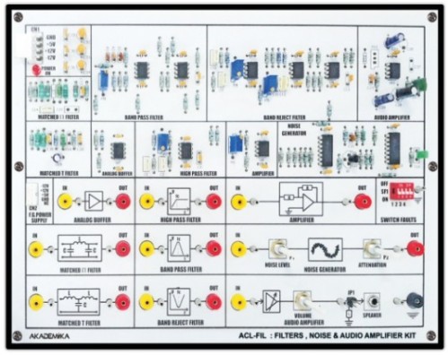
About Product
The ACL-FLS Filters, Noise & Audio Amplifier Kit enables students to perform practical experiments on noise generation, S/N ratio measurement, and frequency response analysis. It integrates multiple filters, a noise adder stage, and an audio amplifier with a speaker for hands-on understanding of real-world communication system behavior.
Noise Generator.
Matched T and II, High Pass, Band Pass and Band Reject Filters.
Audio Amplifier.
Output amplitude
White noise source
Output amplitude: Adjustable from 0 ~ 3V p-pSignal Attenuation Network
Adjustablefrom 0 to the maximum of input value
Signal+ Noise Adder stageAudio Amplifier with Loud Speaker
Output power: 0.5 W
Speaker: 8 OHM, 0.3 WFilters
High Pass Filter
3.4KHz cutoff
Band Pass Filter
FrequencyRange 7 ~ 13KHz
Band Reject Filter
Frequency Range 7 ~ 13 KHz
Matched Filter
p section: 20 KHz cutoff
T section: 20 KHz cutoffInput voltage
0~ 2V p-p
Output voltage
0~ 2 Vpp
Switch faults
4switch faults are provided on board to study different effects on circuit
Interconnection
2 mm banana socket
Test points
Test points are provided on board to observe intermediate signals
Power Supply
GND,+5V, +12V, -12V
Examine the operation of a noise generator.
Examine the operation of a signal attenuation network.
Measurementof S/N ratio.
Measurement of noise figure.
Measurement of the frequency response and power output of an audio amplifier.
To calculate the frequency response of high pass, band pass band reject and matched ( T and p section) filters.
With 35 years of legacy in Technical Education, Akademika extends its expertise to Defence and Skill development, building Innovative, Reliable Training Systems for the next generation of Learners.
Partner with Akademika
Join leading institutions that trust our engineering to Advance Learning and Research.