Defence Technology
Radar Training Laboratory
About Product
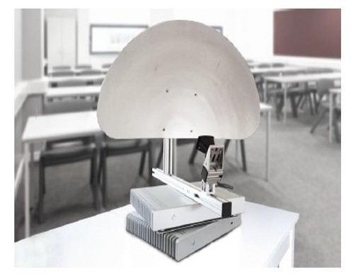
The Radar Training System is a real, safe-to-use pulse + FMCW radar platform designed for close-range object detection, SAR imaging, Doppler studies, and radar data classification. It supports multiple concurrent users and provides real-time radar signals for training, research, and machine-learning applications.
Real-time modular system with a facility for a minimum of 5 concurrent users to access the radar. (Expandable to 100 Users using a cloud server)
Teacher logs in to start the radar, and students can log in to conduct exercises independently in real time.
Allows users to manipulate live and pre-recorder IQ data from the Radar and work independently on the Modular Block diagram editor-based software with large libraries of Scopes, filters, and algorithms.
Allows students to play on the Radar Signal Conversion Chain by changing signal conversion functions like STC, DC Suppress, MTI, etc., at different stages concurrently and independently—web-based software with A-Scope, B-Scope, PPI, RCS estimation, CFAR, MTI, filters, window functions, and Doppler tools. Reads I/Q data and interfaces with MATLAB.
View multiple A-scopes, B-scopes, and PPI-scopes at various stages of the radar block diagram, enabling the comparison of the results and analysis of the results.
Modular for future upgrades by adding Modules like Air Traffic Control Modules to meet the requirements of ATCO (Air Traffic Controller) and ATSEP (Air Traffic Security Electronics Personal) curriculum.
NextGen 8 GHz Pulse Radar Training System
Technical Specifications
Range Resolution: better than 10.6 cm
Range: up to 30 m (when using the parabolic reflector)
Tx center frequency (ETSI / KCC): 7.29 GHz / 8.748 GHz
Tx bandwidth (ETSI): 1.4 GHz
Pulse Width: 0.5 nsec (Gaussian)
Peak Pulse output power (ETSI): -0.7 - 6.3 dBm
Max pulse repetition frequency. 90 Hz
Rx sampling rate: 23.3 GS/s
Rx gain (ETSI): 12.3 - 15 dB
Rx noise figure (ETSI): 5.4 - 8.8 dB
Rx noise figure (ETSI): 5.4 - 8.8 dB
Deliverables
- one (1) transceiver and antenna unit 8 GHz,
- one (1) digital signal processing unit (DSP)
- one (1) horn-shaped antenna with adjustable inclination
- one (1) parabolic reflector with adjustable inclination
- one (1) motor control unit (only activated when rotary unit is added)
- one (1) cable set.Target Positioning Module
In contrast to traditional target tables, the target is not spatially limited. The system is able to carry various radar targets that are connectable to the target system without the requirement of any tools. Different targets/materials representing various radar cross‐sections (RCS) are supplied with the Radar Training System, including a corner reflector (retro‐reflector) consisting of three mutually perpendicular, intersecting flat surfaces and two spheres. The device is able to rotate to rotate the reflectors representing various cross sections.
Deliverables
One (1) Wireless Mobile track vehicle, including batteries
One (1) remote controller, including batteries
Three (3) targets (01- Corner Reflector and 2 Spheres of different diameter )Local Web-Server based Radar Control andData Analysis Software ( FreeScope )
Algorithms & Filters
Air Traffic Control Module
Understanding the main components of a radar system
Familiarize yourself with the A-scope, B-scope & PPI scope of radar.
Measuring the Range Resolution of the Radar .
The Radar Equation.
Showing the dependence of the transmitter power and the amplitude.
Showing the dependence of the target’s distance (range) and the amplitude.
Showing the dependence of the antenna gain and the amplitude.
Radar Cross Section.
Showing the dependence of target size and the amplitude.
Showing the dependence of the target angle and the amplitude.
Showing the dependence of the target shape and the amplitude.
Showing the dependence of the target material and the amplitudeSensitivity Time Control.
Constant False Alarm Rate (CFAR) 1D and 2D
Comparing static threshold and 1D and 2D CFAR
Cleaning the PPI Screen with CFAR.Moving the Target Indication (MTI).
Raw I and Q Signals .
I and Q Signals in Radar Applications.
Understanding the Relationship of Movement and IQ Signals.Measuring the Antenna Beam Width.
Measure the beam antenna half-power beam width.
Introduction to the dB Scale.
Measure the half-power value in dB.
FFT and the Doppler Effect.
Generating plots and tracks as required as defined in ICAO DOC 4444.
Improve the traditional moving target indication MTI with an image-enhancing post processing
Conduct moving target detection MTD and understand the difference to MTI
Apply MTD with Doppler Filter and understand the difference to another movement analysis algorithms
Apply and analyze standing person recognition algorithms as required e.g. in autonomous mobility
Creating own complex filters for moving or standing targets
Improving or varying known composite algorithms
Improving the radar image by adding additional processing
With 35 years of legacy in Technical Education, Akademika extends its expertise to Defence and Skill development, building Innovative, Reliable Training Systems for the next generation of Learners.
Partner with Akademika
Join leading institutions that trust our engineering to Advance Learning and Research.